Walpersdorfer Str. 38
91126 Schwabach
Tel.:
+49 (0)9122 - 63148-0
Fax.:
+49 (0)9122 - 63148-29

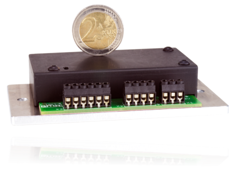
Frequency converter SFU 400



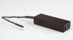
USB adapter:

Technische Daten Technical specifications
SFU
400
Versorgungsspannung
Power Supply
Anschluss / connection: X1 Schraubklemmen für Litzen oder Drähte bis
/ screw terminals for strands or wires up to 0,75 mm²
24 V…48 V DC (+10 %) / 7 A mit PE Anschluss an / with PE connection at X1
Kein Verpolschutz / No protection against faults due to reversed polarity
Sicherungen
Fuses
FS1: intern 7AT/63V SMD
empfohlene externe Absicherung / recommended external fusing: 6AT
Dauerausgangsleistung
Continuous Output Power
380 VA / S1 – 100 %
Spindelanschluss
Spindle Connection
Anschluss / connection: X2 Schraubklemmen für Litzen oder Drähte bis
/ spring clamps for strands or wires up to 0,75 mm²
3-pol.: U, V, W, mit PE Anschluss an / with PE connection X2
Ausgangsspannung
Output Voltage
max. 32 V AC
Ausgangsstrom
Output Current
Phasendauerstrom / phasen current 7 A
Bremschopper
Brake Chopper Resistor
integriert / on board 54 Ω / 4 W / Einsatzspannung / threshold voltage: 54 V
Ausgangsfrequenz
Output Frequency
AC: 1.666 Hz / max. 100.000 Upm rpm @ 2pol Spindle
Steueringänge
Control inputs
Anschluss / connection: X3 – Schraubklemmen für Litzen oder Drähte bis
/ screw terminals for strands or wires up to 0,75 mm²
Digital In: Start / Stop ( 0 / 24 V ) "0" = 0…5 V, "1" = 13…24 V
zulässiger Spannungsbereich / permissable voltage range -3 V…30 V DC
Imax @ 24 V = 10 mA
Analog In: Drehzahl Sollwertvorgabe / duty value rotational speed ( 0…10 V ) Min-Max
Rin: 60 kΩ, 10 bit
PTC, KTY, PT1000 Temperatursensor Spindel, Schaltschwelle einstellbar / temperature
sensor adjustable
Steuerausgänge
Control outputs
Anschluss / connection: X3 – Schraubklemmen für Litzen oder Drähte bis
/ screw terminals for strands or wires up to 0,75 mm²
2 x Digital Out: Open Collector; 45 V/0,5 A nicht kurzschlussgeschützt
no short circuit protection
induktive Lasten müssen mit externen Dioden abgesichert werden
inductive loads must be protected externally by diodes
Schnittstellen Interface
Anschluss/ connection: X4 RS232, 115 kBd
Betriebsanzeigen
Operating status indicators
2 x LEDs grün / rot, 2 x LEDs green / red
Statusanzeige in verschieden Blinkcodes / status display with different blink codes
max. Maße B x H x T (mm)
max. dimensions W x H x D (mm)
73 x 53 x 14 mm, auf Montageplatte / on mounting plate 100 mm x 55 mm x 22 mm
Gewicht
Weight
120 g
Betriebsbedingungen
Operating conditions
5 °C – 40 °C / no condensation
•
Sensorless operation of asynchronous and synchronous motors
•
Speed frequencies up to 100.000 rpm (1666 Hz)
•
Continuous output power: 380 VA / S1 – 100%
•
Digital signal processor (DSP)
•
On board chopper brake resistor
•
High precision sinusoidal output signals with a low distortion
factor and low deformation allow for optimal rotation qualities
in AC motors of all operating conditions
•
All parameters like power, voltage and frequency are collected
in real time and are regulated by the implemented vector
control depending on the load.
•
High operating safety: All operating conditions like acceleration,
operation with nominal rotation speed, braking are controlled
and critical conditions are intercepted.
•
Short circuit protected
•
Protection against excess temperature

SFU 400

Technische Daten Technical specifications
SFU
400
Versorgungsspannung
Power Supply
Anschluss / connection: X1 Schraubklemmen für Litzen oder Drähte bis
/ screw terminals for strands or wires up to 0,75 mm²
24 V…48 V DC (+10 %) / 7 A mit PE Anschluss an / with PE connection at X1
Kein Verpolschutz / No protection against faults due to reversed polarity
Sicherungen
Fuses
FS1: intern 7AT/63V SMD
empfohlene externe Absicherung / recommended external fusing: 6AT
Dauerausgangsleistung
Continuous Output Power
380 VA / S1 – 100 %
Spindelanschluss
Spindle Connection
Anschluss / connection: X2 Schraubklemmen für Litzen oder Drähte bis
/ spring clamps for strands or wires up to 0,75 mm²
3-pol.: U, V, W, mit PE Anschluss an / with PE connection X2
Ausgangsspannung
Output Voltage
max. 32 V AC
Ausgangsstrom
Output Current
Phasendauerstrom / phasen current 7 A
Bremschopper
Brake Chopper Resistor
integriert / on board 54 Ω / 4 W / Einsatzspannung / threshold voltage: 54 V
Ausgangsfrequenz
Output Frequency
AC: 1.666 Hz / max. 100.000 Upm rpm @ 2pol Spindle
Steueringänge
Control inputs
Anschluss / connection: X3 – Schraubklemmen für Litzen oder Drähte bis
/ screw terminals for strands or wires up to 0,75 mm²
Digital In: Start / Stop ( 0 / 24 V ) "0" = 0…5 V, "1" = 13…24 V
zulässiger Spannungsbereich / permissable voltage range -3 V…30 V DC
Imax @ 24 V = 10 mA
Analog In: Drehzahl Sollwertvorgabe / duty value rotational speed ( 0…10 V ) Min-Max
Rin: 60 kΩ, 10 bit
PTC, KTY, PT1000 Temperatursensor Spindel, Schaltschwelle einstellbar / temperature
sensor adjustable
Steuerausgänge
Control outputs
Anschluss / connection: X3 – Schraubklemmen für Litzen oder Drähte bis
/ screw terminals for strands or wires up to 0,75 mm²
2 x Digital Out: Open Collector; 45 V/0,5 A nicht kurzschlussgeschützt
no short circuit protection
induktive Lasten müssen mit externen Dioden abgesichert werden
inductive loads must be protected externally by diodes
Schnittstellen Interface
Anschluss/ connection: X4 RS232, 115 kBd
Betriebsanzeigen
Operating status indicators
2 x LEDs grün / rot, 2 x LEDs green / red
Statusanzeige in verschieden Blinkcodes / status display with different blink codes
max. Maße B x H x T (mm)
max. dimensions W x H x D (mm)
73 x 53 x 14 mm, auf Montageplatte / on mounting plate 100 mm x 55 mm x 22 mm
Gewicht
Weight
120 g
Betriebsbedingungen
Operating conditions
5 °C – 40 °C / no condensation
















![[x]](index_htm_files/close.png "Schließen")

